Switching your car’s electrical charging system from a dynamo to an alternator is a popular conversion and, as Rob Woodall explains, there are some pretty good reasons for doing so…
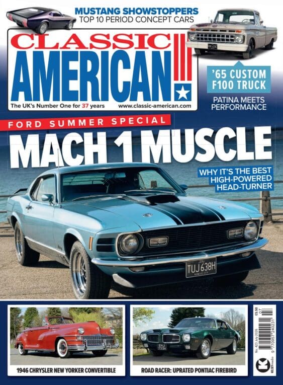
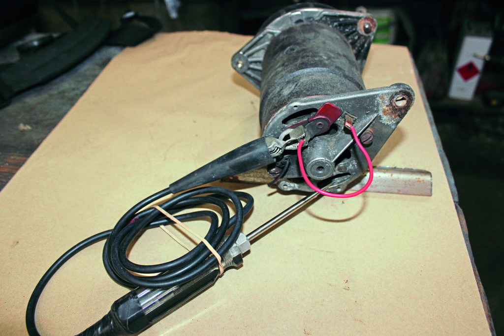
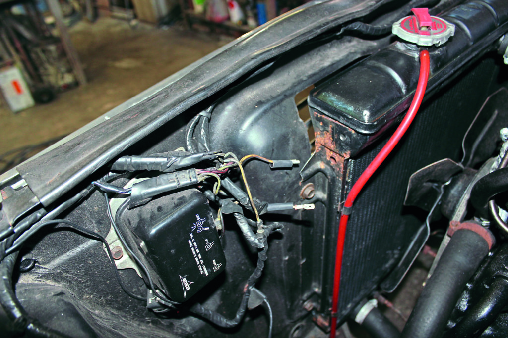
If your classic American car has a dynamo charging system, provided originality isn’t the main consideration, then changing the dynamo and regulator for an internal control alternator is an easy upgrade. In the case of this ’64, six cylinder Falcon, the original dynamo had previously been replaced with a British Ford Lucas unit, complete with its brittle plastic pulley! This dynamo had ceased charging due to worn-out brushes; a simple enough fix, and one I remember doing often enough.
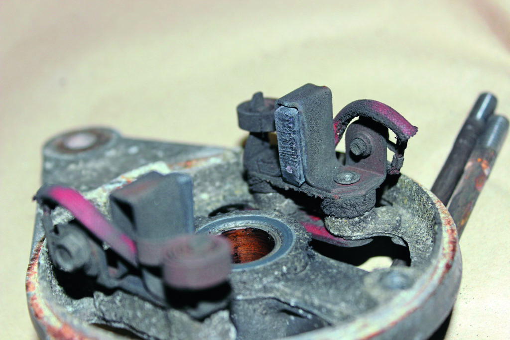
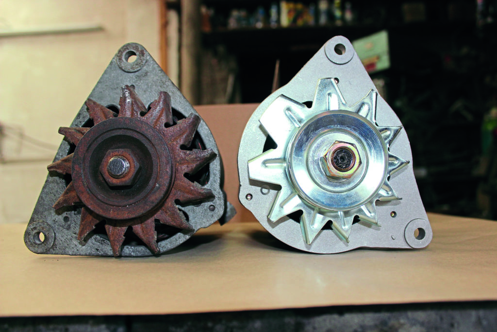
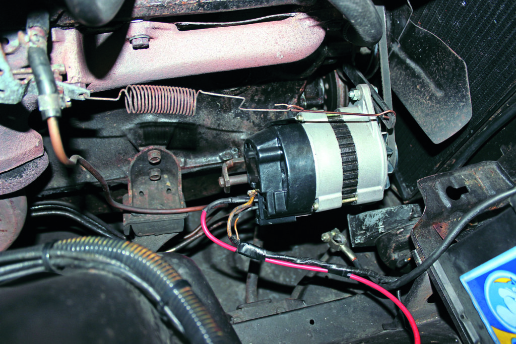
There are a number of advantages of alternators over dynamos − because of their internal design they can be run at higher speeds, providing almost full output at engine idle. This is a serious consideration if you have fitted an electric radiator fan or any other power-sapping accessories. I’ve chosen to install the well-known Lucas type ACR alternator; it was one of the first types that replaced dynamos back in the Seventies. It’s particularly suited to classics as it only requires two wires; the main output wire and the warning light wire.
Enjoy more Classic American Magazine reading every month.
Click here to subscribe & save.
Since the original dynamo also used two wires, it may have had a precautionary earth wire, but it’s easy to rejig the connections.
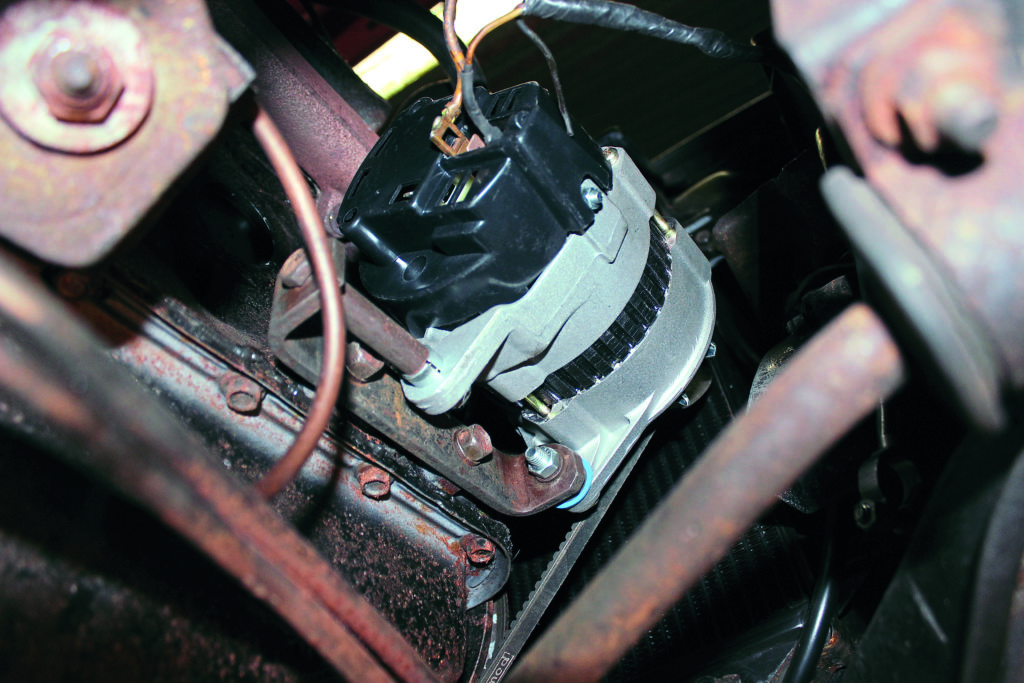
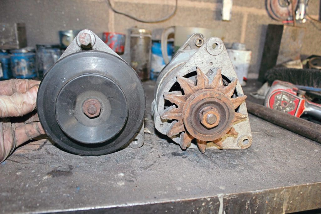
Fitting the alternator will probably require some alteration to the engine mounting bracket and the adjustment stay. These are normally bolted to the engine, which does make modification easier.
These ACR units are available in right- or left-hand mountings, so it’s best to check out the engine mounting layout first. Be sure to have the alternator pulley exactly in line with the other pulleys or it will result in a short belt life.
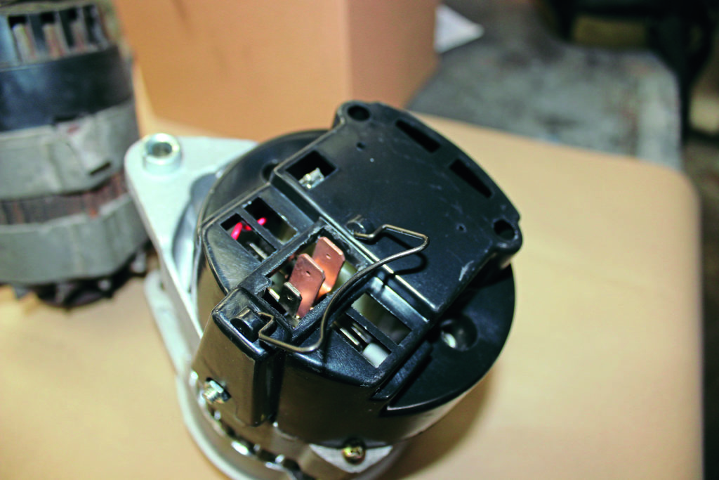
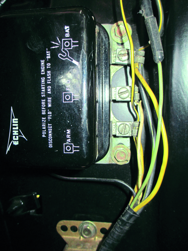
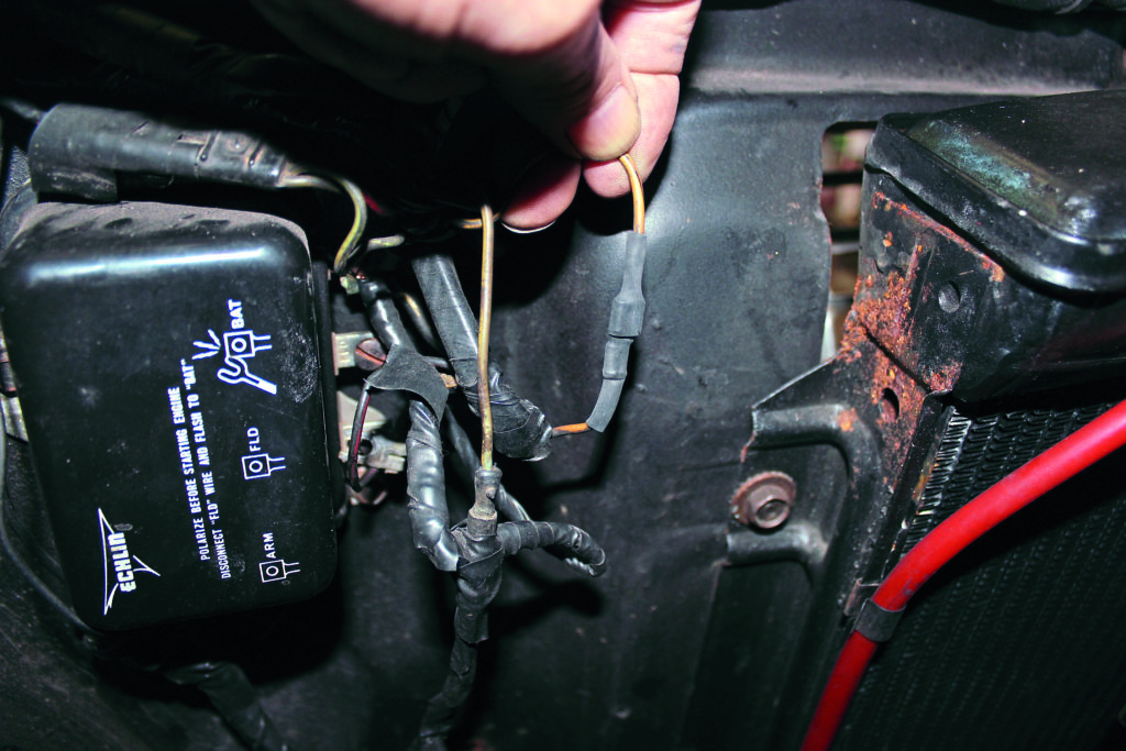
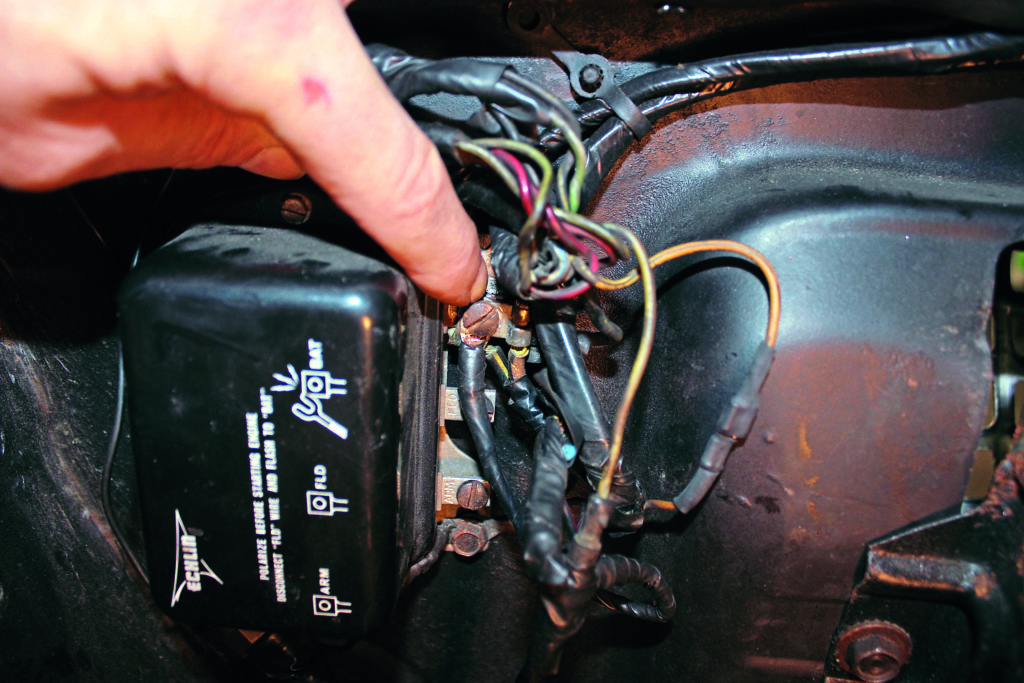
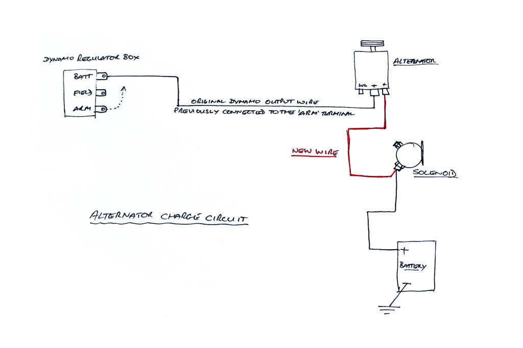
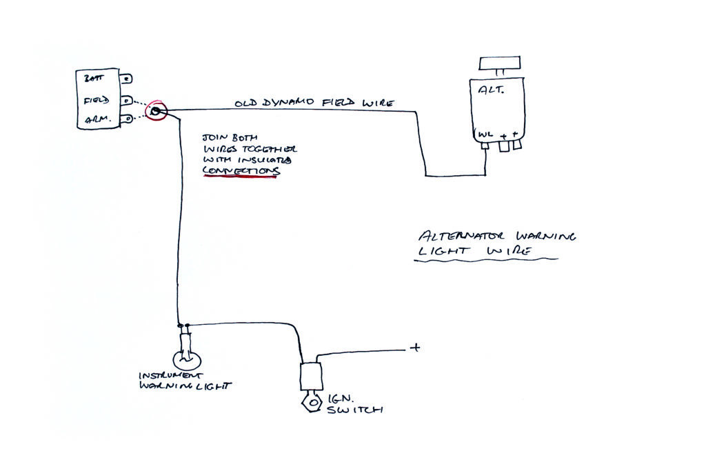
These alternators require a warning light to operate so the dash warning light needs to be checked to see that it illuminates when its regulator connection is earthed with the ignition on. The regulator will have a wire connected to the dynamo which may be marked ‘field’ or ‘fld’; this can be coupled to the old dynamo warning light wire to be reused for the alternator instrument warning lamp. The old dynamo output wire can be connected to either of the alternator’s large spade output terminals.
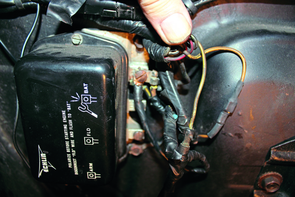
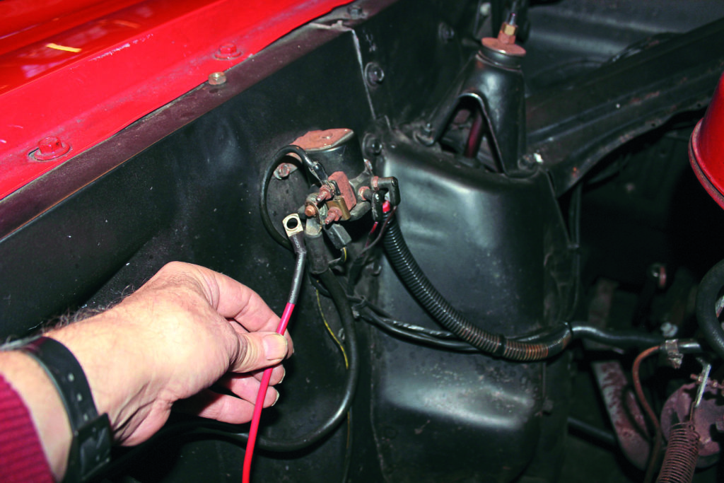
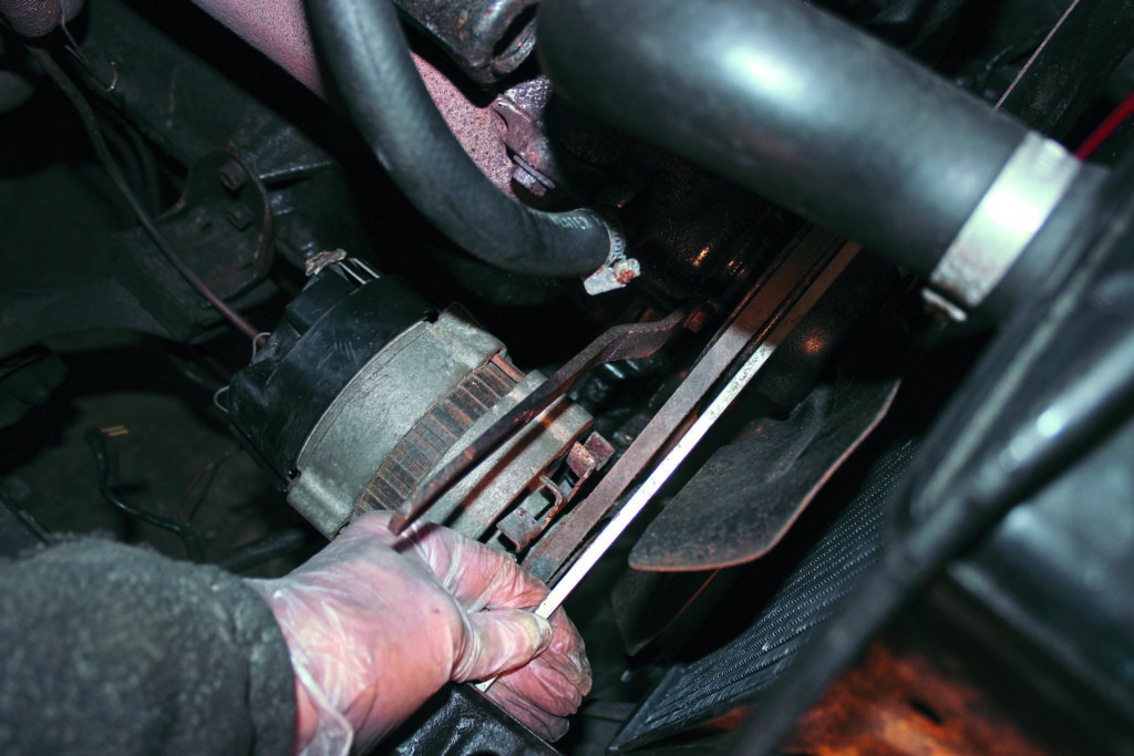
At the regulator box, the dynamo output wire, on the ‘arm’ connection, should now be connected on to the ‘bat’ terminal, leaving any other existing wires connected. This alternator has almost double the old dynamo output, so I’ve connected another heavy gauge wire directly to the solenoid battery terminal. A different fan belt will probably be needed; these are available in various lengths. A new belt will likely require retightening after running, as it beds to the pulleys. Fully charge the battery before the new alternator is fitted.
Words and photography: Rob Woodall